First nozzle iteration for the ZA-125: OpenMotor simulation, two-piece nozzle design, material decision matrix and the start of CNC machining.
Project
ZA-125 Experimental Rocket Motor
Entry
01
Class date
Tue 20 Oct 2026
Phase
Design → Fabrication
Author
Arturo
Instructor
S. Gurgel
Subsystem
Nozzle & motor case
Status
In progress
01 Goal / Objectives
Goal: Design and begin fabricating a two-piece nozzle (graphite throat insert in an aluminum carrier) for the ZA-125 motor, and set the pressure the motor case must be designed to.
Simulate motor performance in OpenMotor with the first nozzle iteration.
Use the predicted peak chamber pressure to set the motor case design pressure.
Choose a nozzle material using a weighted decision matrix.
Design the two-piece nozzle and generate CNC toolpaths for the carrier.
Make a drilling guide for the radial bolts that retain the nozzle.
02 Criteria / Constraints
Table 1 · Nozzle and case requirements
Type
Requirement
Reason
Constraint
Machinable on a 3-axis CNC mill
Available shop equipment
Constraint
Not brittle at the radial bolt holes
Nozzle is retained by radial bolts through the case
Criterion
High-temperature resistance at the throat
Throat sees the highest heat flux
Criterion
Wear (erosion) resistant
Throat diameter must stay constant to hold chamber pressure
Criterion
Reusable across multiple firings
Lower cost per test
Constraint
Safe: case rated at least 2× max expected pressure
Margin for uncontrolled variables such as propellant casting quality
03 Analysis
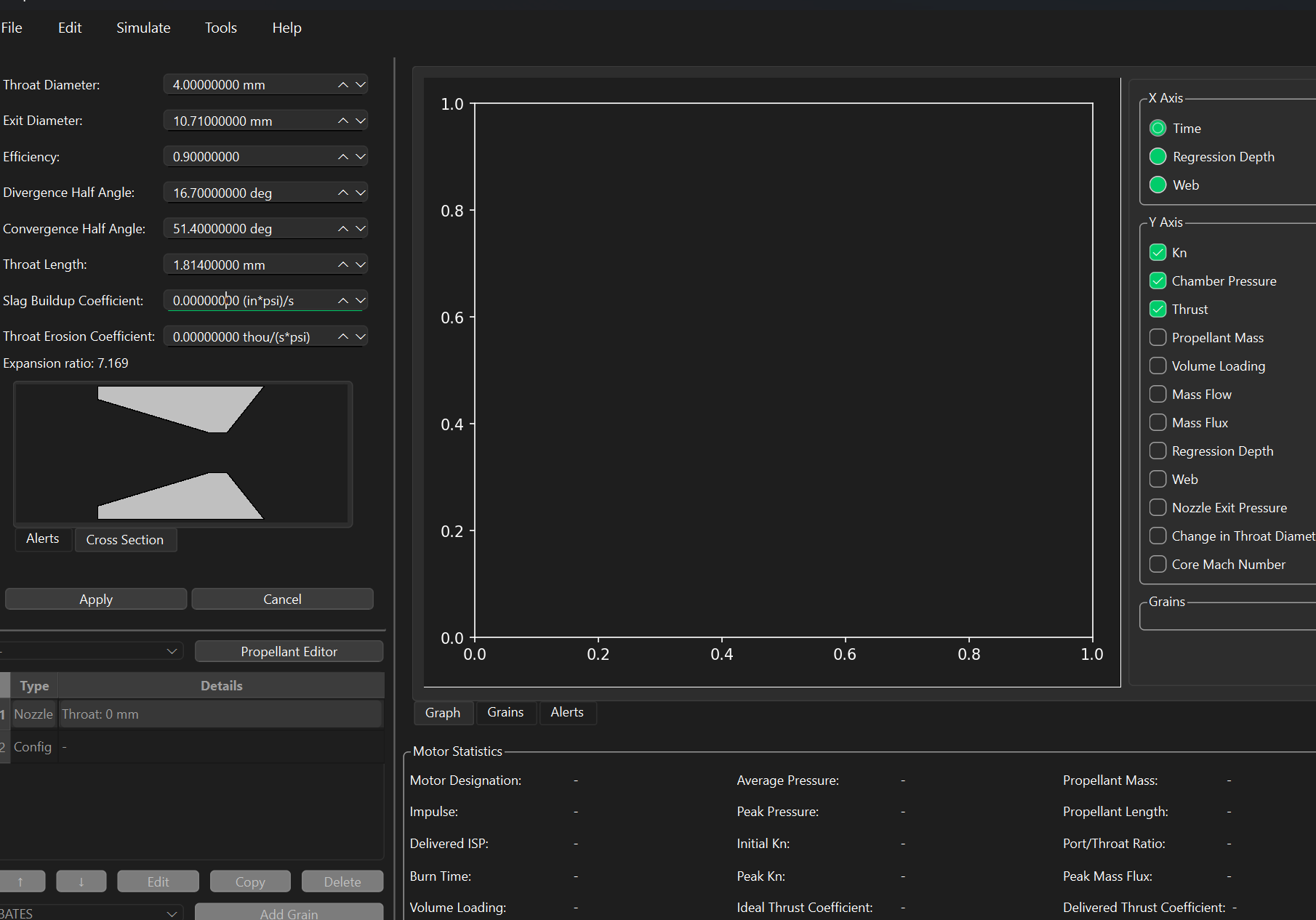
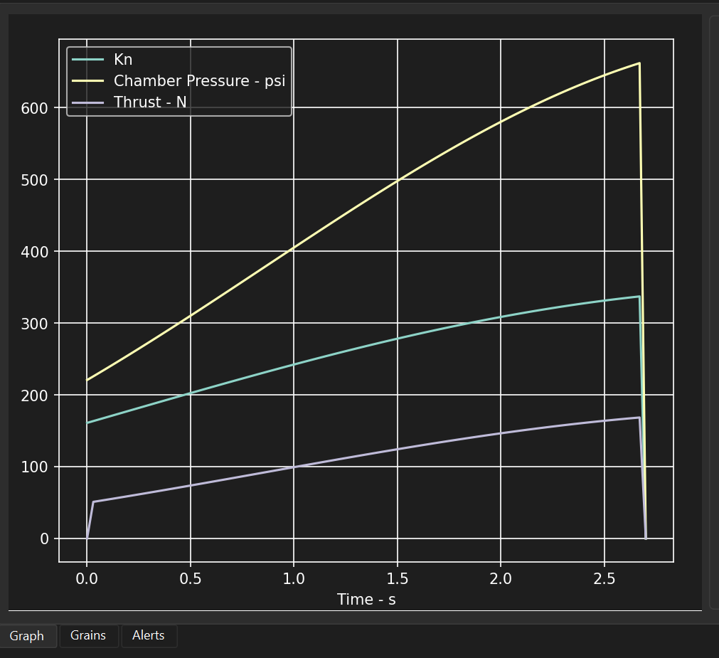
The motor was modeled in OpenMotor with the first nozzle iteration (Fig. 1). The simulation (Fig. 2) shows chamber pressure rising across the burn and peaking just before burnout. The maximum pressure should stay below, but close to, 800 psi. The motor case wall must therefore be at least double the thickness required to hold 800 psi, giving a 2× safety factor.
Table 2 · Nozzle iteration 1 inputs (OpenMotor)
Parameter
Value
Throat diameter, Dt
4.000 mm
Exit diameter, De
10.710 mm
Expansion ratio, ε = Ae/At
7.169
Divergence half-angle
16.7°
Convergence half-angle
51.4°
Throat length
1.814 mm
Nozzle efficiency
0.90
Table 3 · Simulated performance (read from Fig. 2)
Result
Value
Burn time
≈ 2.7 s
Peak chamber pressure
≈ 660 psi
Peak thrust
≈ 168 N
Kn (start → end)
≈ 160 → 337
Design pressure limit
800 psi
Case design pressure (2× limit)
1,600 psi
04 Material Decision Matrix
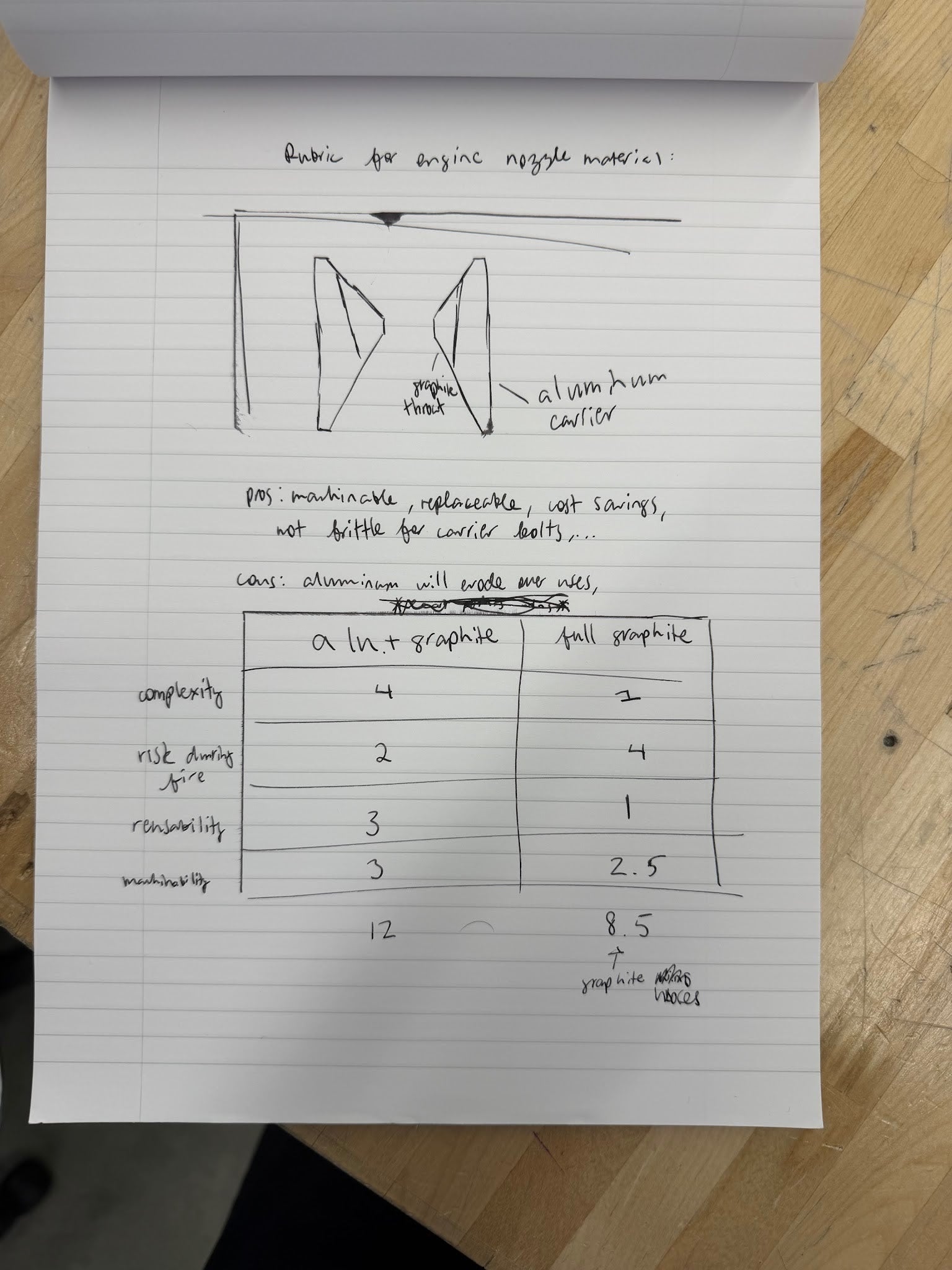
Two nozzle concepts were compared: an aluminum carrier with a graphite throat insert, and a nozzle machined entirely from graphite. Each criterion was scored 1–4, higher is better (Fig. 8).
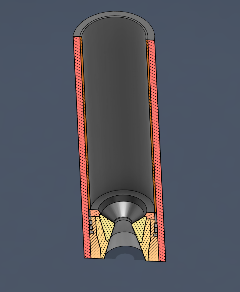
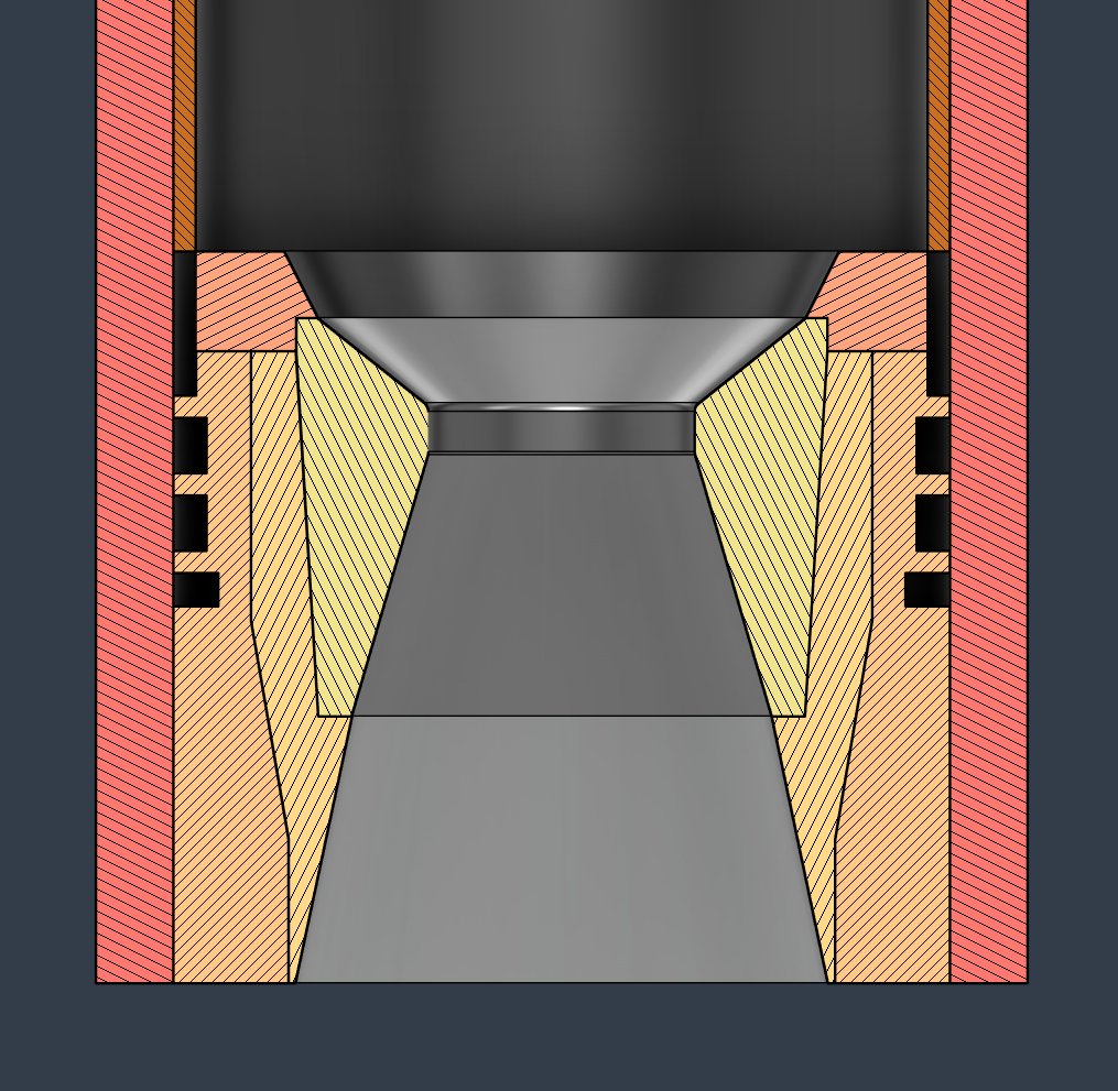
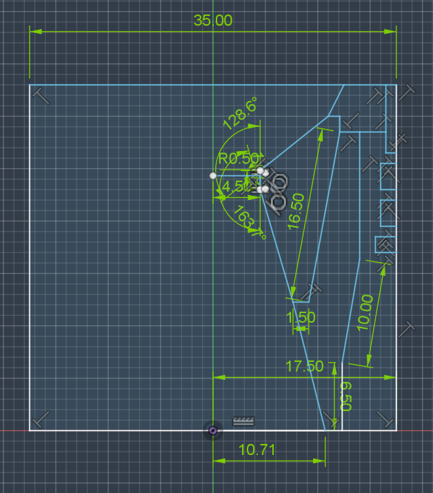
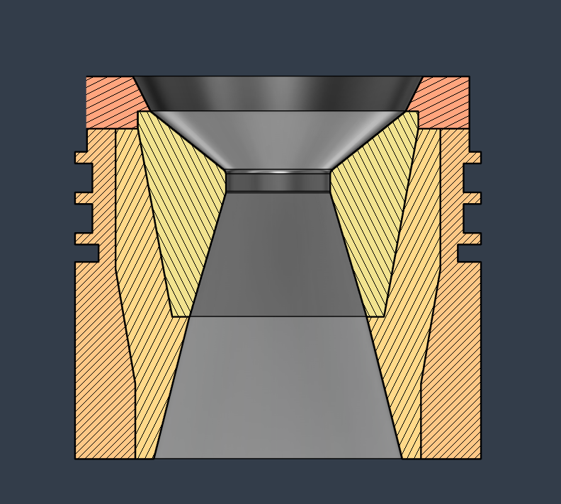
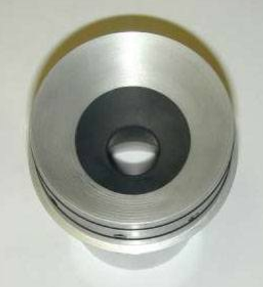
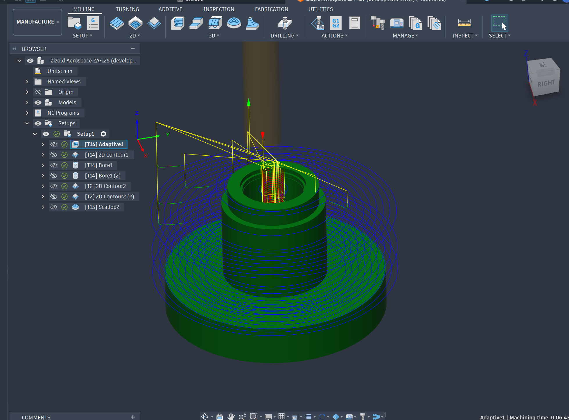
Fig. 1OpenMotor nozzle inputs for iteration 1. Throat 4.00 mm, exit 10.71 mm, expansion ratio 7.169.Fig. 2Simulated Kn, chamber pressure (psi) and thrust (N) vs. time. Pressure peaks near 660 psi at about 2.7 s.Fig. 3Section view of the full motor: casing, phenolic liner, propellant chamber and two-piece nozzle.Fig. 4Nozzle seated in the motor case, showing the graphite throat insert inside the aluminum carrier.Fig. 5Dimensioned nozzle profile sketch (mm). 35.00 mm outer diameter, R0.50 throat radius.Fig. 6Two-piece nozzle assembly, section view. The graphite insert carries the converging section and throat.Fig. 7Reference design: graphite throat insert pressed into a metal nozzle housing.Fig. 8Hand-drawn concept sketch and decision matrix for nozzle material (typed up in Table 4).Fig. 9Fusion CAM toolpaths for the 6061-T6 nozzle carrier: adaptive clearing, 2D contours, bores and scallop finish.
08 Results & Next Steps
The aluminum carrier with a graphite throat scored highest (12 vs. 8.5) and was selected. Stock material has been bought, toolpaths are complete and machining of the carrier has started. The motor case will be designed for 1,600 psi, twice the 800 psi limit.
Finish machining the aluminum carrier and record measured dimensions.
Machine the graphite throat insert and test its fit in the carrier.
Finish the drilling guide for the radial bolts.
Order the motor casing and phenolic liner.
Calculate the required case wall thickness for 1,600 psi.
Choosing a selection results in a full page refresh.